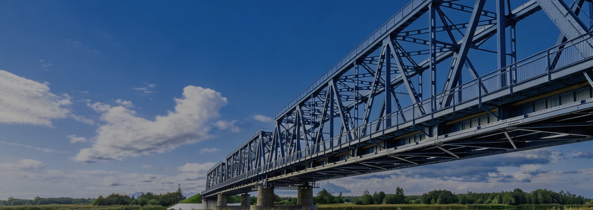
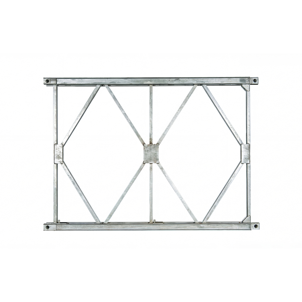
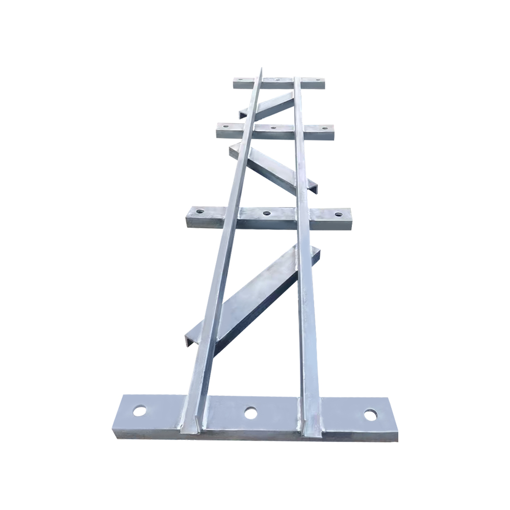
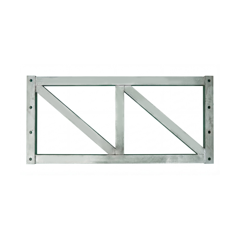
If you have ever watched a bridge appear across a river in a matter of days, you have seen a bailey bridge truss doing quiet, unglamorous work. The truss is the load-bearing heart of the whole system: a steel panel, repeated and pinned together until a line of identical frames becomes a span strong enough to carry trucks, plant, or an entire construction site's traffic. The idea is beautifully simple, and that simplicity is exactly why it has survived for more than eighty years.
What follows is a practical walk through the truss itself, how the panels are built, where the Type 321 and Type 200 families differ, and how to decide which configuration suits your project. We design and manufacture these components every day, so the perspective here is deliberately hands-on rather than theoretical.
What Exactly Is a Bailey Bridge Truss?
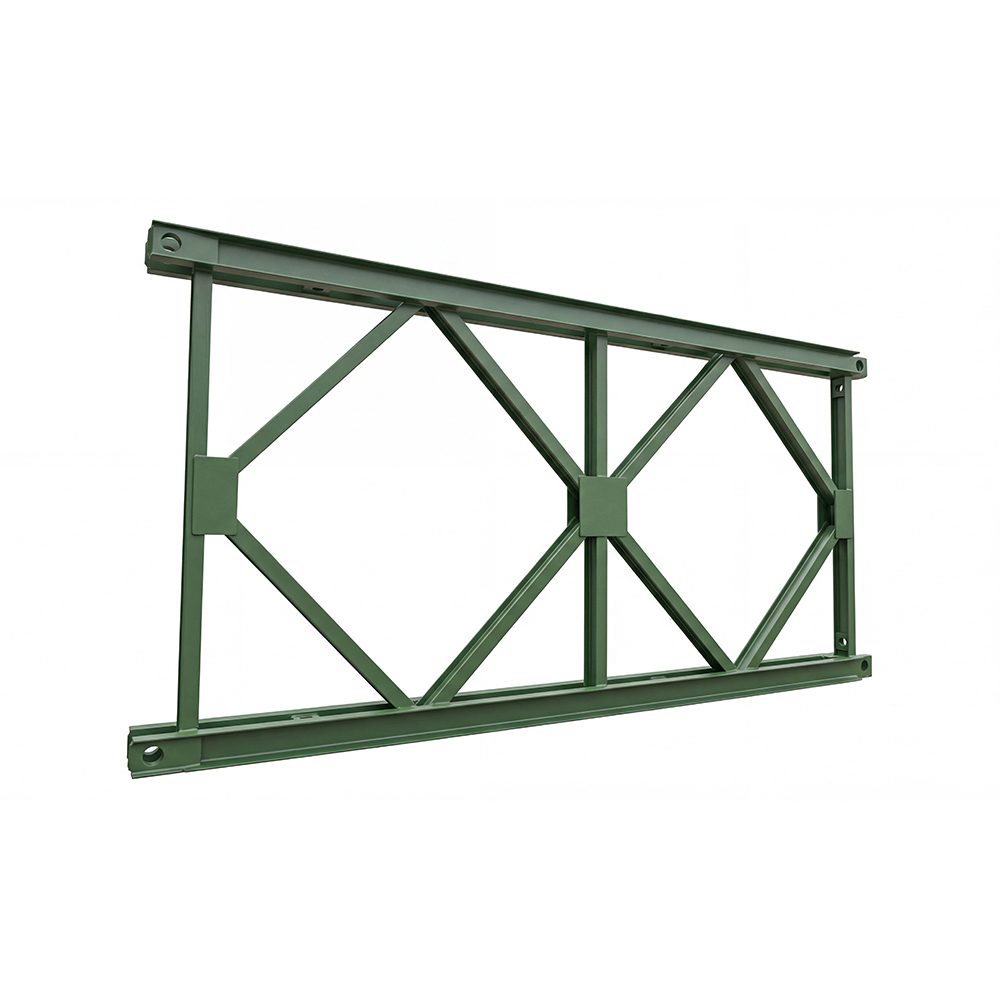
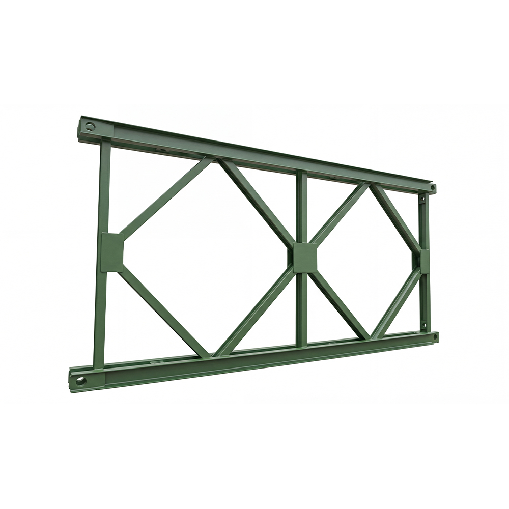
A bailey bridge truss is the vertical side panel that forms the main girder of a bailey bridge. Each panel is a steel frame roughly three metres long, built from top and bottom chords, verticals, diagonals, and a regular pattern of holes punched along the chords. Those holes are the key to everything. They allow panels to be joined end to end with panel pins, doubled up in height, or set two and three rows deep, all using the same basic part.
Because the geometry never changes, the truss behaves like a building block. A short footbridge might use two panels per side. A long, heavily trafficked crossing might use dozens per side. The capacity of the bridge does not come from one large member; it comes from how many identical trusses you line up and how carefully you connect them.
That modular logic is what makes erection so fast. Panels can be carried by hand or light plant, launched from one bank without cranes, and later dismantled and reused on another site. For a broader look at how the design has developed over time, our article on the engineering excellence behind bailey steel bridges covers that history in more depth.
Inside a Standard Truss Panel
Look closely at a single panel and you will find four working parts doing four different jobs:
- Top and bottom chords, the horizontal members that carry bending forces, one side in compression and the other in tension.
- Verticals, the short struts that hold the chords apart and stiffen the panel against shear.
- Diagonals, the web members that move shear from one chord to the other and give the panel its characteristic triangulated appearance.
- Pin holes and chord holes, the connection points for panel pins, bracing frames, and reinforcement chords, all drilled to a standard pattern so that any panel fits any other.
Because every hole follows a fixed template, panels from different production batches stay interchangeable. That is a genuine advantage on site, where a damaged panel can be swapped out without reworking the connection. It also means the quality of a truss depends heavily on manufacturing tolerance. Hole alignment, weld consistency, and straightness matter far more than the outward appearance of the steel.
Type 321 and Type 200: Two Truss Families
The two families you will meet most often are Type 321, the original pattern, and Type 200, usually written as HD200. They share the same modular philosophy but differ in panel depth, steel section, and how much load a single truss line can carry. The table below compares the two as we build them.
Comparison of the two bailey truss families we manufacture; use it as a starting point for a conversation, not as a final specification.
| Characteristic |
Type 321 truss |
Type 200 (HD200) truss |
| Standard panel module |
3.05 m (10 ft) |
3.05 m (10 ft) |
| Connection system |
Standard panel pins |
Standard panel pins |
| Relative panel depth |
Shallower, lighter chords |
Deeper, heavier sections |
| Reinforced variant |
321 reinforced bailey truss |
HD200 reinforced bailey truss |
| Bracing components |
321450 support frame |
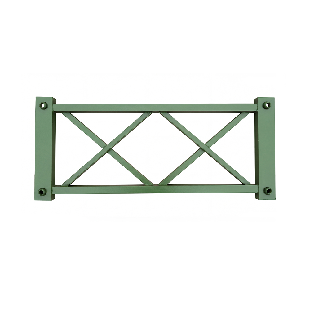
Horizontal and vertical support frames |
| Deck and crossbeam parts |
321 panel and crossbeam |
HD200 panel and crossbeam |
| Typical duty |
Short to medium spans, access and support beams |
Longer spans and heavier wheel loads |
In practice, Type 321 is the workhorse for site access, temporary crossings, and cast-in-place support beams. HD200 comes into its own when spans stretch out or when the loads on the deck are genuinely heavy, because the deeper panel gives more stiffness for the same span and reduces deflection under load.
Reinforced Trusses and How Capacity Grows
When a standard truss line is not quite enough, the first move is usually reinforcement rather than replacement. Reinforcement chords, additional steel members bolted along the top and bottom chords, raise the bending capacity of a panel line without changing its length or connection geometry. The bridge gets stronger while the erection sequence stays almost exactly the same.
That is the idea behind the reinforced truss panels we produce, which are built to the same pin pattern as the standard panel and can therefore be mixed into an existing truss line without modification.
 Type 321 Reinforced Chord for Bailey Bridge TrussesA Q355B reinforcing chord that rigidly connects upper and lower chords to boost mid-span bending stiffness while matching standard Type 321 pin patterns.View Product →
On real projects, reinforcement is often concentrated in the middle third of a span, where bending moments peak, while the ends of the bridge stay standard. That keeps weight and cost down where they are not needed. It also means a reinforced panel must match the standard panel precisely in hole position, because the reinforcement is only as effective as the connection that carries its force back into the main chords.
Pre-Cambered Trusses and Deflection Control
Every steel beam deflects under load, and a bailey bridge is no exception. On a long span that deflection can be visible: a sag in the deck line that looks alarming even when the structure is perfectly sound. Pre-cambering deals with this by building a slight upward curve into the truss, so the bridge starts a little high and settles to level under its design load.
Pre-cambered trusses are manufactured with the curve formed into the panel rather than forced in on site, which keeps the running surface predictable and avoids stressing connections that were never designed for it.
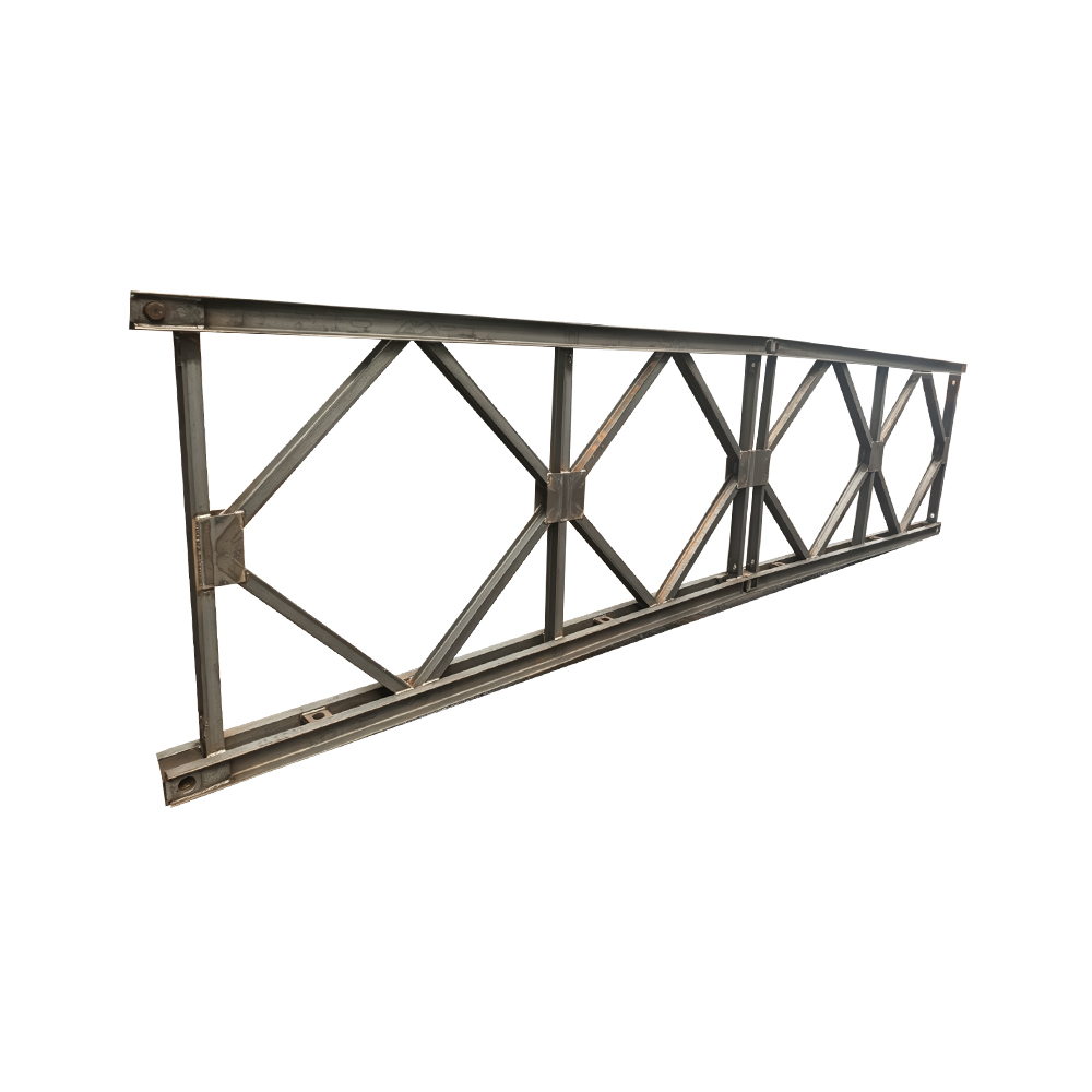 Pre-Cambered Bailey Truss Systems for Controlled DeflectionType 321 and Type 200 pre-cambered truss series with built-in curve to offset deflection and support level running surfaces on demanding spans.View Product →
They are typically specified where a level surface matters most: bridges carrying regular vehicle traffic, structures supporting formwork where a level soffit is required, and long spans where drainage falls or appearance must be controlled. If deflection is a concern on your project, it is worth raising early, because camber is much easier to design in than to add later.
Trusses Beyond Bridges: Support, Formwork, and Gantries
Not every bailey bridge truss ends up over a river. The same panels are widely used as longitudinal beams in temporary works: cast-in-place support systems carrying formwork over a road or watercourse, jacking formwork platforms, and launching gantries for bridge erection. The loading is much the same as in a bridge girder; the difference is that the deck above is a formwork table rather than a roadway.
Heavy support applications often call for the deeper Type 200 line, where the extra depth delivers more stiffness and less movement under wet concrete. Support frames, both horizontal and vertical, brace the truss lines together and keep them plumb and evenly spaced, which matters a great deal when the load above is a large pour.
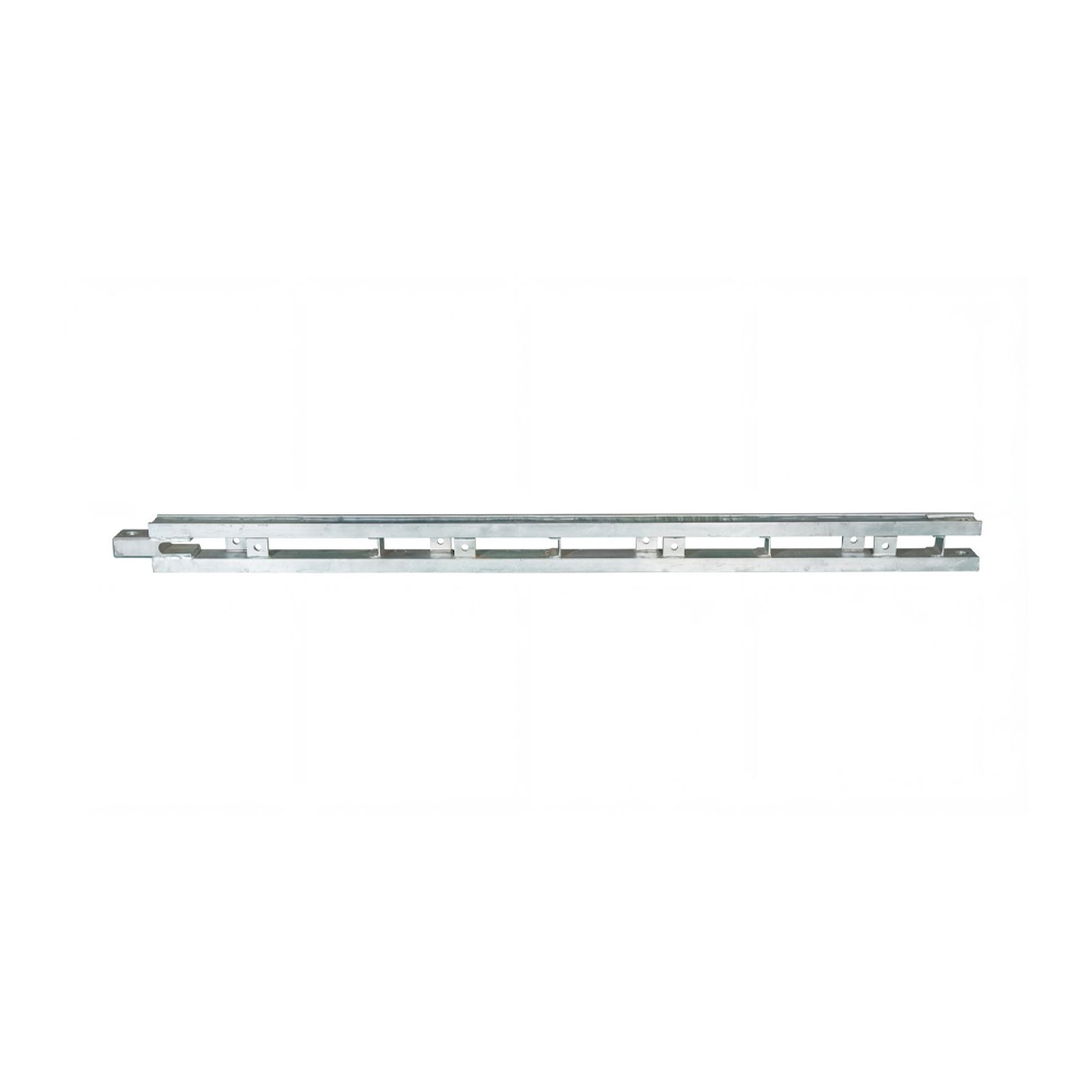 Type 200 Reinforced Chord for Heavy-Duty Bailey TrussesA Q355B reinforcing chord for HD200 truss lines, increasing bending stiffness and deformation resistance in large-span, heavy-load formwork and bridge applications.View Product →
This reuse of a single component across very different jobs is the quiet strength of the system. If you would like to see how that plays out in the field, our piece on why bailey steel bridges remain the cornerstone of temporary and emergency crossings looks at the applications in more detail.
Choosing the Right Truss Configuration
When clients ask us which truss to use, the conversation usually follows a predictable path. The questions that decide it are:
- Span: how far between supports, and will there be intermediate piers?
- Load: what will actually cross the structure, and how often?
- Deflection limit: how level does the running surface need to stay?
- Erection method: can you launch from one bank, or do you have crane access?
- Reuse: is this a one-off crossing or an asset you plan to move between sites?
- Timing: how quickly do you need the components on site?
Answering those six questions usually narrows the choice to one truss family, one reinforcement arrangement, and a rough panel count within a few minutes. If you can also tell us the soil conditions at the abutments and whether the bridge will carry tracked plant, we can normally suggest a workable layout on the first reply.
A bailey bridge truss rewards understanding. It is a standard part used in a non-standard way, and almost every design question comes back to the same three variables: span, load, and how much deflection you are willing to live with. Get those right and the rest of the system, crossbeams, support frames, deck panels, and bracing, falls into place around them.
We have been manufacturing and supplying these components since 2017, and we are always happy to talk through a specific crossing, a support scheme, or a rental arrangement. Reach us at sales@jhbaileybridge.com or +86-511-88881818, and send a sketch of your site if you have one. A short conversation at the planning stage is usually worth more than any amount of rework later.


 Français
 Español
 عربى