The Bailey bridge is one of the most significant engineering achievements of the 20th century, originally developed for military use during World War II and now widely deployed in civilian infrastructure projects across the globe. Understanding Bailey bridge specifications is essential for structural engineers, military logistics planners, and construction project managers who need reliable, portable, and rapidly deployable bridging solutions. This guide provides a comprehensive breakdown of standard technical parameters, load classifications, span configurations, and material requirements.
Origins and Design Philosophy
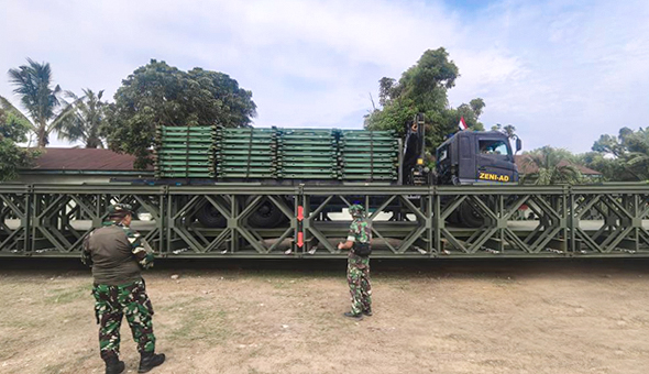
Designed by Donald Bailey in 1940 and first manufactured by the Mabey & Johnson company, the Bailey bridge was conceived as a modular panel bridge that could be assembled by a small team without the need for heavy cranes or specialised equipment. Its genius lies in the standardised steel panel system, which allows individual components to be carried by hand and assembled into spans capable of supporting heavy military vehicles.
The design philosophy centres on three principles: modularity, scalability, and field repairability. Each panel is interchangeable, meaning damaged sections can be replaced without dismantling the entire structure. This adaptability made the Bailey bridge a cornerstone of Allied operations in North Africa, Italy, and Western Europe—and it remains in active use by dozens of militaries and civil authorities today.
Key fact: During World War II, Allied forces constructed an estimated 3,000 Bailey bridges, covering over 490,000 feet of bridging. Field Marshal Montgomery reportedly called it "the bridge that won the war."
Standard Panel Dimensions and Material Specifications
The foundational unit of a Bailey bridge is the standard panel. All other specifications—span length, load capacity, and configuration type—derive from this base component. The panels are fabricated from high-tensile steel conforming to established military and civilian standards (typically BS EN 10025 Grade S355 or equivalent ASTM A572 Grade 50).
Standard panel dimensions
| Parameter |
Metric |
Imperial |
| Panel length |
3.048 m |
10 ft |
| Panel height |
1.473 m |
4 ft 10 in |
| Panel width (single chord) |
0.058 m |
2.3 in |
| Panel weight |
273 kg |
601 lb |
| Top & bottom chord depth |
203 mm |
8 in |
| Diagonal member diameter |
50.8 mm |
2 in |
Table 1 — Standard Bailey bridge panel dimensions (BS 5400 / NATO STANAG 2021 reference)
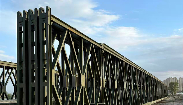
Panels are connected via steel pins of 57 mm diameter, enabling rapid assembly without welding or bolting. The lattice-truss design distributes loads efficiently through the diagonals and verticals, achieving a high strength-to-weight ratio that is critical for both portability and structural performance.
Deck and transom specifications
The deck system consists of transoms (cross-beams), stringers (longitudinal beams), and timber or steel chess boards (deck planks). Each transom spans between the two opposite truss panels and is secured by transom clamps. Standard chess boards are typically 63 mm thick hardwood or, in modern variants, steel chequer plate panels.
| Component |
Dimensions (mm) |
Unit weight (kg) |
| Transom |
4,420 × 152 × 102 |
82 |
| Stringer |
3,048 × 102 × 76 |
41 |
| Chess board (timber) |
1,372 × 356 × 63 |
25 |
| Ramp bay panel |
3,048 × 1,473 |
341 |
| Base plate |
914 × 508 × 38 |
138 |
Table 2 — Deck system component specifications
Configuration Types and Designation System
Bailey bridge configurations are described using a standardised designation system that encodes the number of panel lines (single, double, or triple), the number of panel stories (single or double), and whether the bridge is built as a through-type or a through-type with top chord reinforcement. The notation typically takes the form SS, DS, TS (Single Story) and DD, TD (Double Story).
Configuration naming conventions
- SS (Single Single): One panel wide, one story tall. Lightest and fastest to build; suitable for foot traffic and light vehicles.
- DS (Double Single): Two panels wide on each side, one story tall. Standard configuration for most wheeled military vehicles up to MLC 30.
- TS (Triple Single): Three panels wide on each side, one story tall. Used for heavier loads on shorter spans.
- DD (Double Double): Two panels wide, two stories tall. Extends achievable span and load class significantly.
- TD (Triple Double): Three panels wide, two stories tall. Maximum configuration; used for MLC 70 tracked vehicles on spans up to 60 m.
NATO MLC (Military Load Classification): Bailey bridge load ratings are expressed in MLC, a NATO standard (STANAG 2021) that classifies vehicles and bridges by gross weight and axle load. MLC 30 corresponds to approximately 30 tonnes; MLC 70 to approximately 70 tonnes.
Span Lengths and Load Capacity Tables
One of the most critical aspects of Bailey bridge specifications is the relationship between span length, configuration type, and allowable load class. The following table provides standard design data based on NATO STANAG 2021 and BS 5400 Part 2 loading criteria.
| Configuration |
Max span (m) |
Max span (ft) |
Wheeled MLC |
Tracked MLC |
| SS |
18.3 |
60 |
MLC 9 |
MLC 12 |
| DS |
30.5 |
100 |
MLC 30 |
MLC 40 |
| TS |
36.6 |
120 |
MLC 40 |
MLC 50 |
| DD |
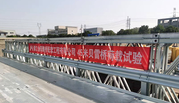
45.7 |
150 |
MLC 50 |
MLC 60 |
| TD |
60.9 |
200 |
MLC 60 |
MLC 70 |
Table 3 — Span length and load capacity by configuration (indicative values; site-specific engineering analysis required)
It is important to note that these values represent maximum design spans for each configuration under standard ground bearing conditions. Actual permissible spans are reduced when the bridge must support continuous convoy traffic, when end bearing soil conditions are poor, or when dynamic impact factors must be applied for high-speed vehicle crossings.
Roadway width specifications
The clear roadway width—the usable carriageway between the inside faces of the main trusses—is fixed at 4.22 m (13 ft 10 in) for all standard single-lane Bailey bridge configurations. This accommodates a single lane of traffic with NATO STANAG vehicle envelopes. Dual-lane variants, achieved by placing two parallel bridge lanes side by side on a common abutment, provide a total roadway width of approximately 8.5 m and are used for high-traffic-volume applications.
Assembly Components and Key Hardware Specifications
The integrity of a Bailey bridge depends not only on the panels themselves but on the precision of its connecting hardware. The following components are specified to tight tolerances to ensure interchangeability across production batches from different manufacturers.
Panel connecting pin
- Diameter: 57.2 mm (2.25 in)
- Length: 184 mm (7.25 in)
- Material: Carbon steel, heat-treated to minimum yield strength of 620 MPa
- Retained by: Split cotter pin, 6 mm diameter
Transom clamp
- Clamping force: Minimum 8 kN when correctly tightened
- Bolt torque: 135 N·m (100 ft·lb) using standard box spanner
- Material: Malleable cast iron or ductile iron GGG-40
Raker (launching nose) specifications
During cantilever launching—the standard assembly method where the bridge is pushed out over the gap from one bank—a lightweight steel nose (raker) is attached to the leading end to prevent the cantilever from tipping. Standard raker lengths are 3.05 m, 6.10 m, or 9.14 m, selected based on total bridge span. The raker must weigh no more than 20% of the main bridge weight to maintain launching balance.
Abutment and Bearing Requirements
The end bearing arrangement is a critical specification that determines the suitability of a site for Bailey bridge installation. The bridge transfers its loads to the ground through base plates and sill beams resting on prepared abutments or natural ground.
Minimum bearing requirements
| Configuration |
Bearing length required (m) |
Min. ground bearing pressure (kPa) |
| SS / DS |
0.91 |
200 |
| TS / DD |
1.22 |
300 |
| TD |
1.52 |
400 |
Table 4 — Abutment bearing specifications by configuration
Where natural soil conditions do not meet the minimum ground bearing pressure, engineers specify granular fill compaction, concrete pad abutments, or driven pile supports. For temporary military deployments on soft ground, steel ground beams or Bailey panel cribs are used to distribute bearing loads.
Important: Inadequate bearing conditions are the most common cause of Bailey bridge structural failures in field deployments. Site investigation including soil classification tests (CBR or plate bearing) must be completed prior to final configuration selection.
Corrosion Protection and Surface Treatment Standards
All Bailey bridge steel components are required to meet specific surface treatment standards to ensure an acceptable service life under field conditions. The standard NATO specification calls for:
- Surface preparation: Shot blasting to Sa 2.5 (near-white metal) per ISO 8501-1
- Primer coat: Zinc-rich epoxy primer, minimum 75 µm dry film thickness (DFT)
- Intermediate coat: Epoxy MIO (micaceous iron oxide), minimum 100 µm DFT
- Finish coat: Polyurethane topcoat in olive drab (RAL 6003) or olive green (FS 34094), minimum 50 µm DFT
- Total DFT: Minimum 225 µm
- Salt spray resistance: 1,000 hours per ISO 9227 with no rusting at scribe line
For permanent civilian bridge installations, many operators upgrade to a full thermal spray zinc (TSZ) system with an elastomeric topcoat, extending the maintenance interval to 25 years. Stainless steel fasteners are also recommended in coastal or marine environments where chloride-induced corrosion is a concern.
Assembly Time and Manpower Requirements
One of the defining advantages of Bailey bridge technology is its rapid assembly capability. Standard military specifications require that a trained combat engineer platoon (approximately 35 personnel) can erect a Double Single (DS) bridge of 30.5 m span within 4 to 6 hours under field conditions. The following table provides general guidance on assembly times for various configurations.
| Configuration |
Span (m) |
Personnel |
Assembly time (hrs) |
| SS |
18 |
16–20 |
2–3 |
| DS |
30 |
30–35 |
4–6 |
| TS |
36 |
35–40 |
6–8 |
| DD |
45 |
40–50 |
8–12 |
| TD |
60 |
50–60 |
12–18 |
Table 5 — Indicative assembly times under favourable daylight conditions with trained personnel
These figures assume no crane support. When mobile cranes or rough-terrain forklifts are available, assembly times can be reduced by 30–40%, particularly for double-story configurations where panel lifting is labour-intensive.
Modern Variants and Upgraded Specifications
The original Bailey bridge design has evolved significantly since 1941. Several manufacturers—including Mabey Bridge, Acrow, and SSBR—now produce enhanced variants that retain the fundamental modular panel principle while offering improved performance characteristics.
Mabey Universal bridge
Mabey's current flagship product introduces high-strength steel panels (S460 grade) that reduce panel weight by approximately 15% while increasing load capacity. Improved deck systems using aluminium alloy decking replace traditional timber chess boards, reducing deck dead load and improving durability in wet environments.
Acrow 700XS
The Acrow 700XS series offers panels measuring 3.05 m × 2.18 m (compared to the standard 3.05 m × 1.47 m), providing a higher moment of inertia per panel. This allows TD-equivalent configurations to achieve spans of up to 75 m and support MLC 80 tracked vehicles—exceeding the limits of the original Bailey specification.
Continuously reinforced deck systems
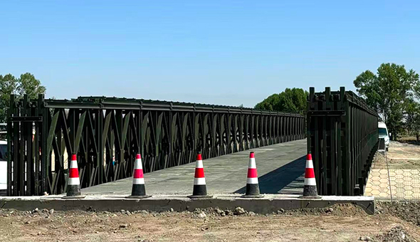
Modern permanent installations increasingly use reinforced concrete deck slabs cast in situ over the Bailey truss system. This composite deck-truss action significantly increases the overall stiffness of the structure and reduces deflection under live loads, meeting the requirements of national highway bridge codes such as AASHTO LRFD or the Eurocodes for long-term civilian traffic.
Inspection and Maintenance Specifications
For bridges in long-term service, whether military or civilian, periodic inspection is mandatory. Standard inspection intervals and criteria are as follows:
- Routine visual inspection: Every 6 months; check for panel deformation, pin wear, deck condition, and coating integrity
- Detailed structural inspection: Every 2 years; includes measurement of chord deflections, pin hole ovality (maximum acceptable wear 3 mm), and weld crack survey
- Major overhaul: Every 10 years or after cumulative MLC equivalent traffic exceeds design thresholds; full disassembly, shot-blast re-coating, and dimensional verification
- Panel replacement criteria: Any panel with chord section loss exceeding 10% of original area, or permanent set exceeding L/500, must be withdrawn from service
Bailey bridge panels are designed to be reused many times across multiple deployments. Military stock panels routinely accumulate 5–10 deployments over a service life of 20–30 years when properly maintained. Civilian operators using panels in fixed permanent installations typically specify a 50-year design life with appropriate fatigue analysis per BS 5400 Part 10.
Applicable Standards and Specifications
Design, manufacture, and deployment of Bailey bridges are governed by a range of national and international standards. Key references include:
- NATO STANAG 2021: Military Load Classification of Bridges, Ferries, Rafts and Vehicles
- AASHTO Standard Specifications for Highway Bridges (for US civilian applications)
- BS 5400: Steel, concrete and composite bridges (UK standard, superseded by Eurocodes but still referenced for legacy structures)
- Eurocode 3 (EN 1993-2): Design of steel structures — steel bridges
- ISO 8501-1: Preparation of steel substrates before application of paints
- ISO 9227: Corrosion tests in artificial atmospheres — salt spray tests
- DEF STAN 01-5 / JSP 434: UK Ministry of Defence specifications for military bridging equipment
Engineers specifying Bailey bridges for permanent civilian use must ensure compliance with the relevant national highway authority requirements, including live load models (HA/HB in the UK, HL-93 in the US), serviceability limits on deflection (typically span/360 under live load), and fatigue life calculations for locations subject to high-cycle dynamic loading.
Bailey bridge specifications encompass a carefully integrated system of panel geometry, material grade, configuration type, load classification, bearing design, and surface protection—each element dependent on the others. Whether the application is a 48-hour emergency military deployment over a washed-out river crossing or a permanent rural highway bridge in a developing country, adherence to established specifications ensures structural safety, predictable performance, and long-term durability.
The enduring relevance of the Bailey bridge—more than 80 years after its invention—is a testament to the power of modular design thinking. As materials technology advances and load requirements grow, updated variants continue to push the boundaries of what was originally conceived on a wartime drawing board, while retaining the fundamental simplicity that made the original design so transformative.


 English
 Français
 Español
 عربى
عربى