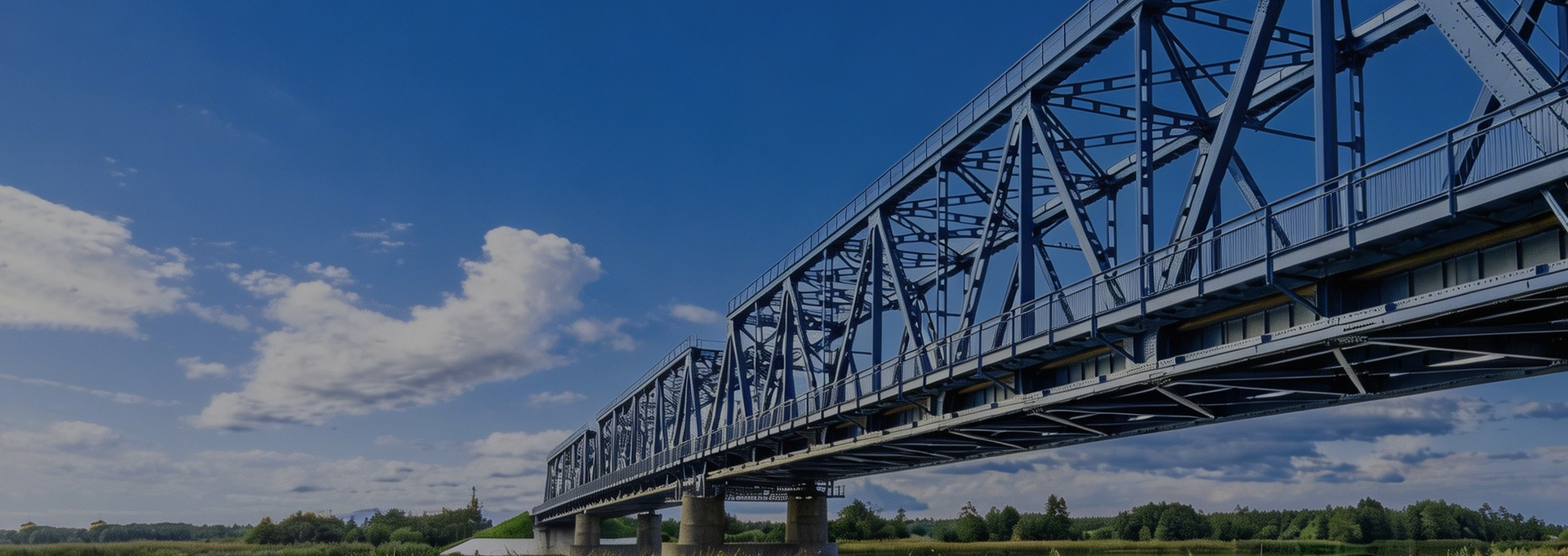
Three weeks after a flood swept out a county crossing, the contractor was asked to restore a 30-metre single-lane bridge before harvest traffic started. A permanent replacement would take months; a Bailey bridge was in service six working days later. That is the reality of bailey bridge construction: a prefabricated steel truss system assembled from standard panels, pins, transoms and bracing, with no welding and no site-made members. The strength of the bridge matters, but the real advantage is speed, and speed depends on how well the construction sequence is planned before the first panel is lifted.
Jinhao builds and erects both major Bailey families, Type 321 and HD200, across temporary access roads, emergency replacements and permanent project staging. The working principle is identical in both systems, so the guidance below applies whether you specify a bridge, rent one, or simply need to manage a supplier with confidence.
What a Bailey bridge construction package contains
Every Bailey bridge starts as a kit of steel components where one bay is identical to the next. The load path is straightforward: wheel loads pass through deck units and crossbeams into two longitudinal trusses, each built from panels pin-connected end to end. In the Type 321 series, a standard panel is roughly 3.05 metres long, about 1.5 metres deep and weighs in the region of 270 kg, light enough for a small crane or a compact crew to handle without heavy erection equipment.
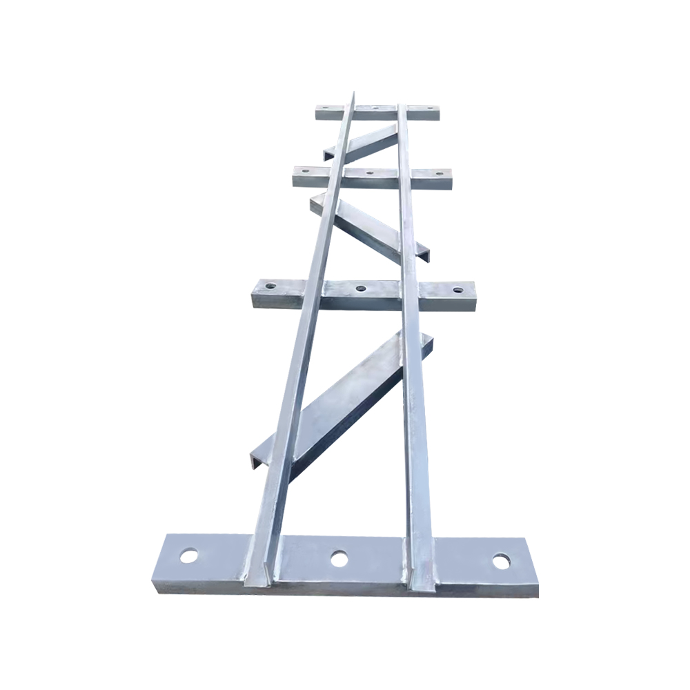
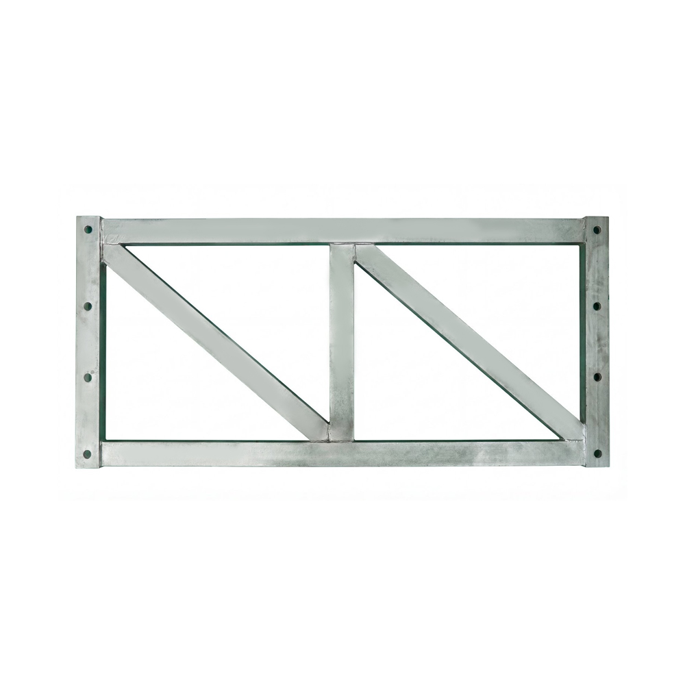
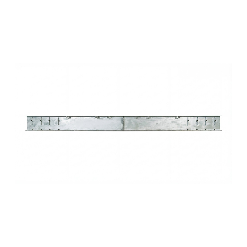
The same principle explains the product range you will encounter when procuring a bridge. Truss panels create the main chord lines; crossbeams distribute load across the full width; stringers and deck units form the running surface; horizontal and vertical support frames lock the trusses at their correct spacing; and reinforced truss sections are added where the plain panel cannot carry the design load.
Typical components in a Bailey bridge kit. The exact list depends on the truss configuration and span.
| Component |
Role in the assembled bridge |
Series availability |
| Truss panel |
Main load-carrying module; pinned end to end to form the truss line |
Type 321 / HD200 |
| Crossbeam (transom) |
Spans across the trusses and transfers deck load to the bottom chords |
Type 321 / HD200 |
| Stringer and deck unit |
Provides the roadway surface and distributes wheel loads to the crossbeams |
Type 321 / HD200 |
| Horizontal support frame |
Keeps truss pairs at correct spacing at bottom chord level |
Type 321 / HD200 |
| Vertical support frame |
Stabilises the trusses laterally at panel points |
HD200 |
| Reinforced truss / chord reinforcement |
Increases bending capacity of an individual truss line |
Type 321 / HD200 |
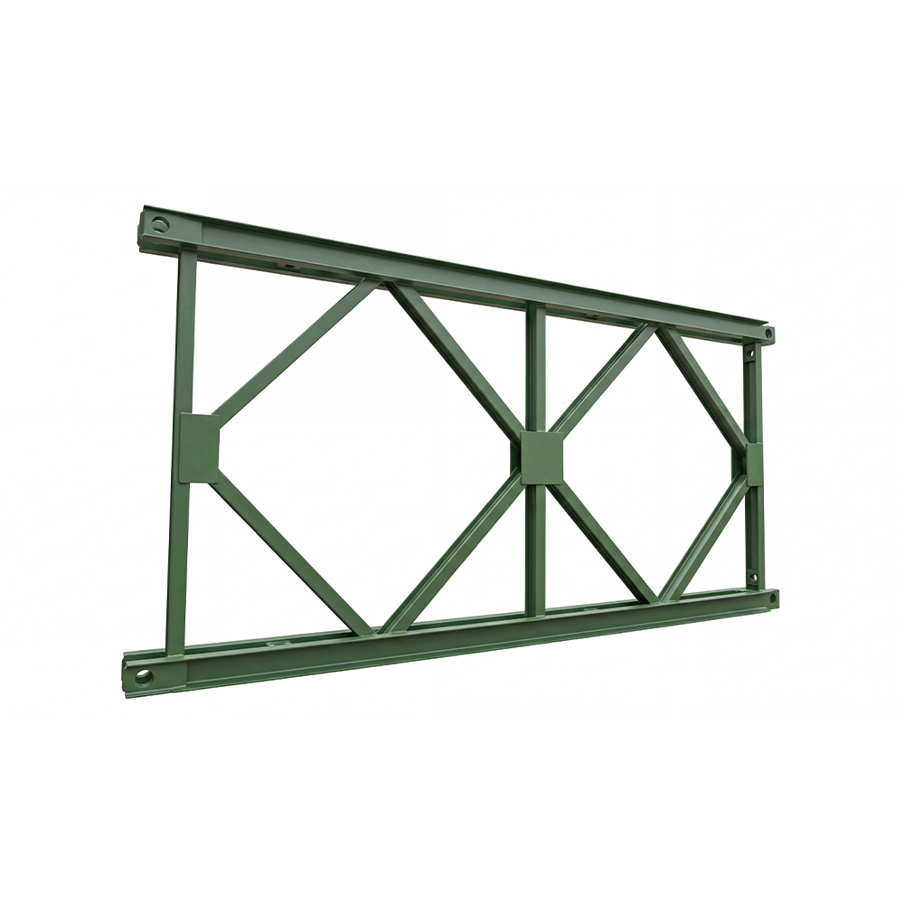
Type 321 is the classic system; it is best known for temporary road bridges and construction-site access, and it remains the most economical choice for clear spans up to roughly 60 metres. All Type 321 panels, crossbeams, reinforced trusses and support frames share the same pin geometry, so components interchange freely between configurations.
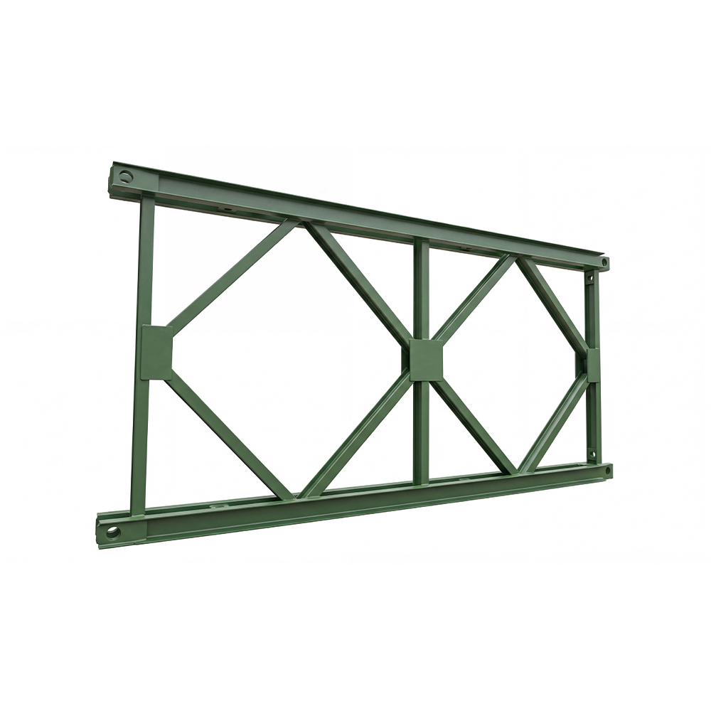 Type 321 Bailey Bridge Panel for Modular Truss SpansThis panel is the core load-bearing element of the classic Type 321 system, featuring welded steel channels and I-beams. It suits temporary road bridges and construction access with clear spans up to roughly 60 meters, offering economical and interchangeable modular components.View Product →
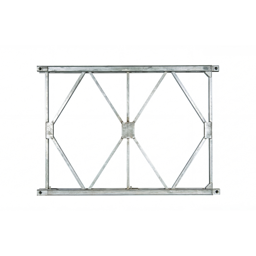
HD200, also referred to as Type 200, is the heavy-duty family. Its panel is taller, around 2.13 metres, and the full component range is sized for larger load classes, which is where the "200" in the name comes from. Projects expecting heavy trucks, crane access on the deck or longer clear spans typically move to the HD200 series. Because both systems follow the same modular logic, capacity can be upgraded by adding truss lines or reinforcement chords rather than by redesigning the bridge.
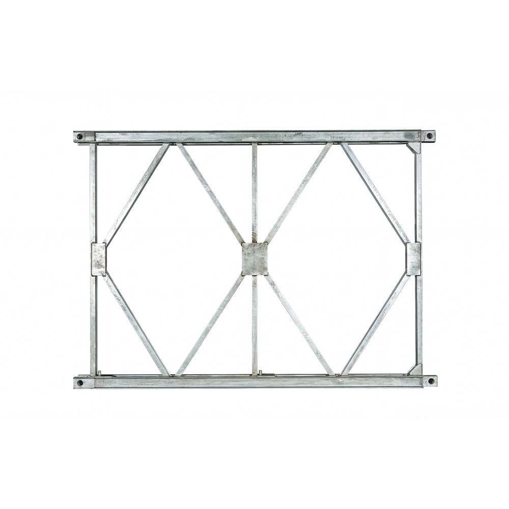 HD200 Bailey Bridge Panel for Heavy-Duty Load ClassesBuilt for larger load classes and longer spans, this taller panel increases bending resistance and reduces deflection compared to Type 321. It suits projects expecting heavy trucks or crane access, and integrates with the same modular framing logic for capacity upgrades.View Product →
The Bailey bridge construction sequence, step by step
Bailey bridge construction looks simple, and that is exactly why it is often underestimated. The entire span is assembled on one bank in three-metre bays, a light launching nose is fitted to the front, and the truss is pushed across the gap on rollers. The governing rule is that every task has a defined order. Our installation crews follow this sequence:
- Survey the site and set out the bearing positions on abutments or piers.
- Prepare bank seats and approach ramps so the bridge lands on solid, level supports.
- Stage the kit bay by bay, checking panels, pins, crossbeams and support frames against the parts list.
- Assemble the trusses on the near bank, pinning panels end to end and fitting bracing frames.
- Attach the launching nose and set up rollers, winch lines and the tail anchorage.
- Launch the assembled truss across the gap, advancing both trusses evenly.
- Install crossbeams, stringers, deck units and handrails once the truss is in position.
- Align the bridge on its bearings and carry out a load test before opening to traffic.
For shorter spans, lifting the assembled truss with a crane is often faster and avoids the need for rollers on the far bank. For longer spans, cantilever launching is the proven method: the bridge is winched forward while the crew adds bays behind, and the launching nose keeps the cantilever moment within the strength of the leading trusses. Winch, rollers and a simple tail anchorage are frequently the only mechanical equipment required.
Deflection deserves attention early in planning. Specifications for temporary road bridges commonly call for vertical deflection in the range of span/400 to span/800, depending on traffic class. Where live load is heavy relative to the clear span, pre-cambered Bailey truss sets compensate for the calculated elastic deflection, so the bridge reaches a level riding position under full load instead of sagging visibly in the middle.
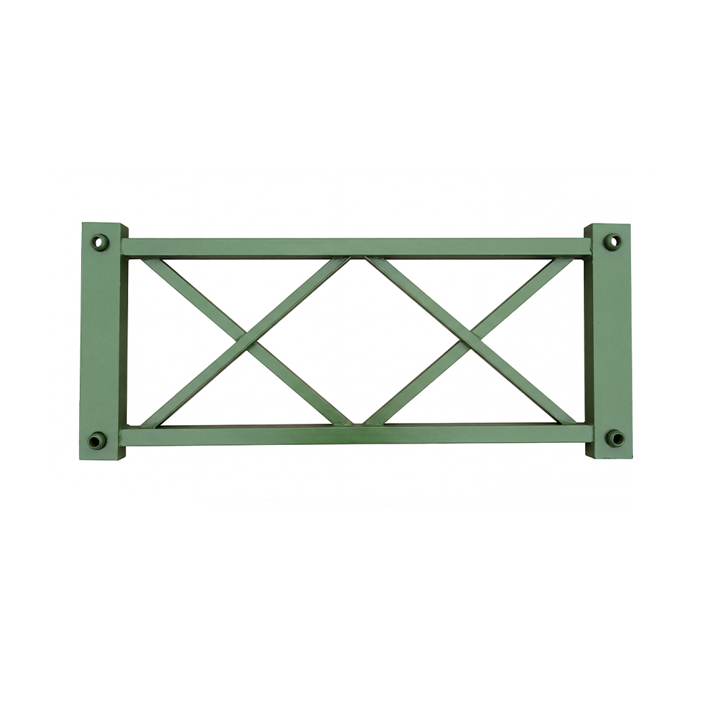
 Pre-Cambered Bailey Truss for Deflection ControlThis truss features an integrated pre-arched structure that compensates for self-weight and load deflection, helping the bridge stay level under full load. It is suitable for large-span demanding scenarios, but pre-camber parameters require calibration before use.View Product →
Matching truss configuration to span and traffic
The key trait of a Bailey bridge is that capacity is changed by adding trusses, not by switching to heavier steel. A standard bridge uses one truss line on each side; a double truss arrangement adds a second line per side; a triple truss arrangement adds a third. Bolting reinforcement chords to the top and bottom of each truss line increases bending capacity further. The selection therefore starts with two numbers: the clear span between bearings and the heaviest vehicle that will cross.
Once those are known, the indicative ranges below help narrow the choice. They are planning values only; every project still needs a proper load calculation for the actual configuration, materials and site conditions.
Indicative clear-span ranges for common truss arrangements. Actual spans must be verified by calculation for the intended traffic class.
| Truss arrangement |
Type 321 typical range |
HD200 typical range |
Typical traffic use |
| Single truss |
15-25 m |
20-35 m |
Light site traffic, utility vehicles |
| Double truss |
25-45 m |
35-60 m |
Single-lane loaded trucks |
| Triple truss |
40-60 m |
50-80 m |
Heavy haulage and diversion routes |
The economic choice is not always the strongest one. For a one-off emergency crossing, renting a standard Type 321 configuration keeps both cost and lead time down; for a site that will stay active for years, purchasing a heavier HD200 configuration often pays off through reuse on later phases. Whatever option you choose, verify that the quoted package includes pins, bolts, crossbeams, support frames and any launch nose components, because they are as essential as the panels themselves.
What to check before contracting a Bailey bridge
Problems on Bailey bridge construction sites are rarely structural and almost always organisational: the wrong parts in the wrong bay, missing pins, or a bearing that was not set square. The following checks prevent the most common issues.
- Confirm the system family, Type 321 versus HD200, and that panels, reinforcement members and support frames are all from the same series.
- Inspect the condition and coating of any reused panels; galvanised coatings must be continuous at pin locations, where wear is highest.
- Ask for the design calculation covering span, traffic class, reinforcement and deflection, rather than relying on generic span tables.
- Verify the list of included parts: pins, bolts, crossbeams, stringers, deck units, support frames and launching nose items.
- Plan the construction layout around the launching direction, including the staging strip behind the near abutment and the crane position.
A second application is worth knowing even if you are not buying a standalone bridge. On many permanent concrete structures, rows of Bailey trusses are assembled on temporary piers to support the formwork of a cast-in-place deck. The trusses carry the full weight of wet concrete, then are stripped and reused once the deck has cured. This is exactly what our cast-in-place Bailey support components are designed for, and it is often where contractors save the most money: the same kit that builds the temporary access bridge also provides the staging for the permanent one.
If you are evaluating the schedule and cost of such an approach, the advantages of modular steel bridges in modern infrastructure development cover the wider project-level benefits in more detail.
Bailey bridge construction performs best when the schedule is short and the planning is thorough; it fails most often when someone assumes that standard parts are self-explanatory and works out the details on site. The difference between those two outcomes is almost always made before the first panel arrives: clear span, traffic class, deflection limit, launching sequence, and a supplier who can handle design, manufacturing, erection and rental as a single package.
At Jinhao, that in-house engineering capability covers the full construction cycle for both Type 321 and HD200 series, including pre-cambered trusses and cast-in-place support solutions. Whether you need a complete bridge, a support staging system, or simply an experienced view on construction method, the first conversation is more productive before the tender closes than after the site does.


 Français
 Español
 عربى
عربى