In 1941, engineers at the British War Office's Experimental Bridging Establishment ran a load test that would define military bridge engineering for decades. They positioned a First World War Mark V tank on a prototype bridge, then placed an A10 Cruiser Mk II on top of it. The structure held without visible distress. This was not just a stress test; it validated a design concept in which flat steel panels, assembled almost entirely by hand, formed a bridge strong enough for armored vehicles.
The prototype was the Bailey bridge, designed by Donald Bailey. It entered production, saw combat use in North Africa in 1942, and became the most widely used military bridge of the war. More than 80 years later, the same modular panel logic still drives the bailey bridge systems used for emergency crossings, construction access, and semi-permanent infrastructure. Understanding what that prototype proved helps engineers and procurement teams make better decisions about modular steel bridges.
The Prototype That Proved the Concept
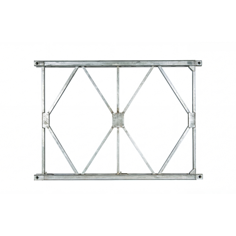
Donald Bailey was a civil engineer at the War Office, and his task was to solve a persistent problem: existing military bridging equipment was too heavy, too slow to assemble, or too specialized for general use. His concept replaced site-welded girders with a standardized truss panel: a welded steel rectangle with pin holes at each corner, designed to be connected end to end and side by side.
The 1941 prototype test with the Mark V and A10 tanks verified three specific things about that concept:
- The pin joints could transmit compression and tension loads reliably even when assembled quickly by hand.
- The bridge did not need a crane or launching girder; it could be pushed across the gap panel by panel on rollers.
- Adding a second story of panels increased load capacity without changing the basic panel design.
Production versions followed the prototype's geometry. A small field team could assemble a 30-meter crossing in under a day. By the end of the war, more than 200,000 panels had been produced, and the design had been licensed and adapted by armed forces around the world.
Design Principles That Survived the Prototype Stage
The three principles validated by the prototype still define how modular steel bridges are engineered and purchased today.
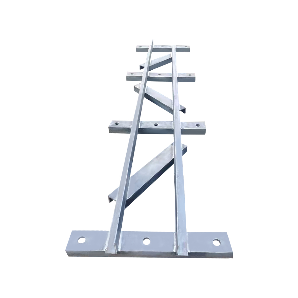
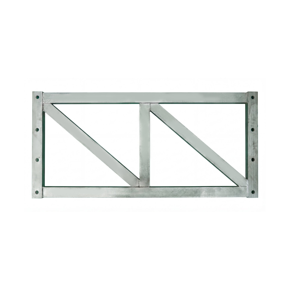
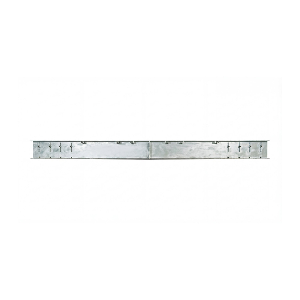
- Standardized components. The panel is the basic unit. Crossbeams, stringers, support frames, and reinforcing chords are all designed to connect to it with the same pins and holes.
- Full interchangeability. Any panel can connect to any other panel regardless of production batch, which demands tight manufacturing tolerances and consistent quality control.
- Progressive launching. The bridge is assembled on rollers and pushed across the gap, allowing installation without heavy lifting equipment in difficult terrain.
These principles apply directly to the two dominant modern systems: Type 321, which follows the classic British geometry, and HD200, a heavier system developed for higher loads and longer spans.
Key differences between Type 321 and HD200 modular bridge systems
| Parameter |
Type 321 |
HD200 |
| Panel height |
1.5 m |
2.1 m |
| Typical span range |
9-60 m |
12-90 m |
| Relative load capacity |
Standard |
Higher |
| Common applications |
Emergency, construction access |
Heavy traffic, railway, longer spans |
The span and load figures in the table are typical planning values rather than fixed limits. Actual capacity depends on panel configuration, number of stories, deck type, and site conditions.
From Wartime Prototype to Modern Engineering Standard
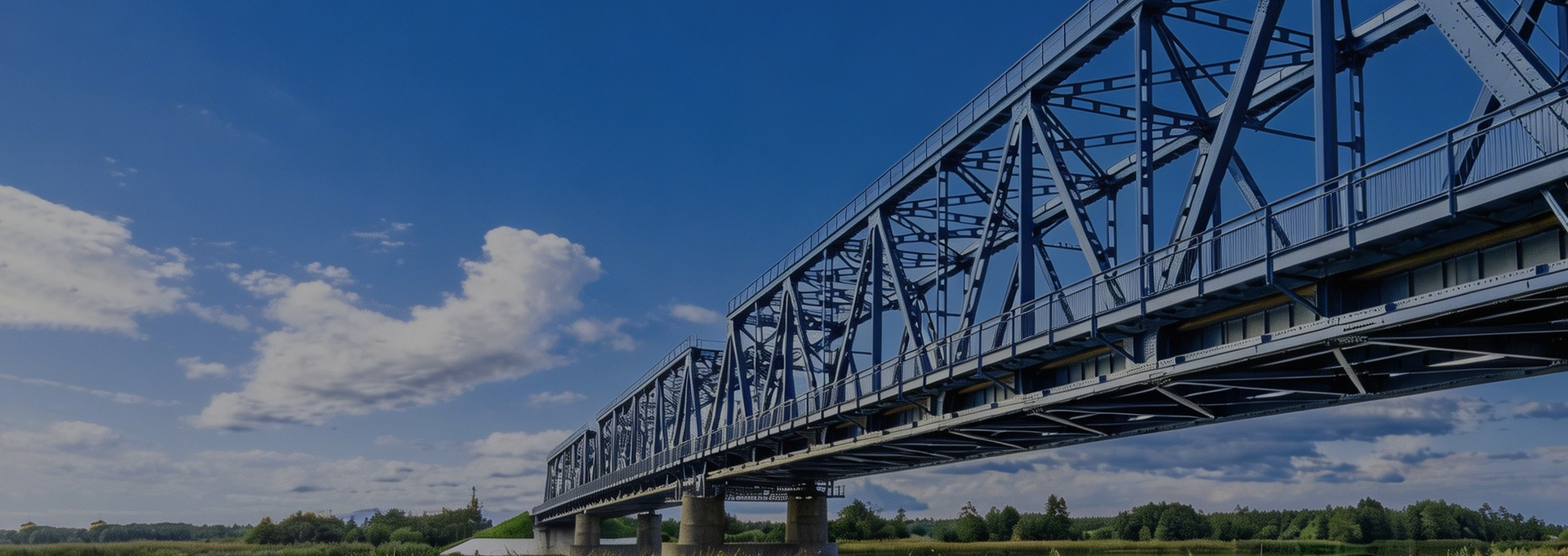
When you look at a modern bailey bridge assembly yard, you are looking at the direct descendant of the 1941 prototype. The panel components used in construction projects and emergency relief operations retain the same pinned connection logic, the same panel-to-panel interchangeability, and the same progressive launching method that Donald Bailey verified with those two tanks.
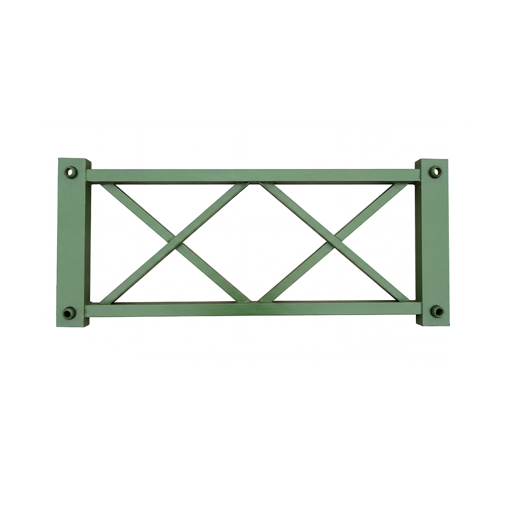
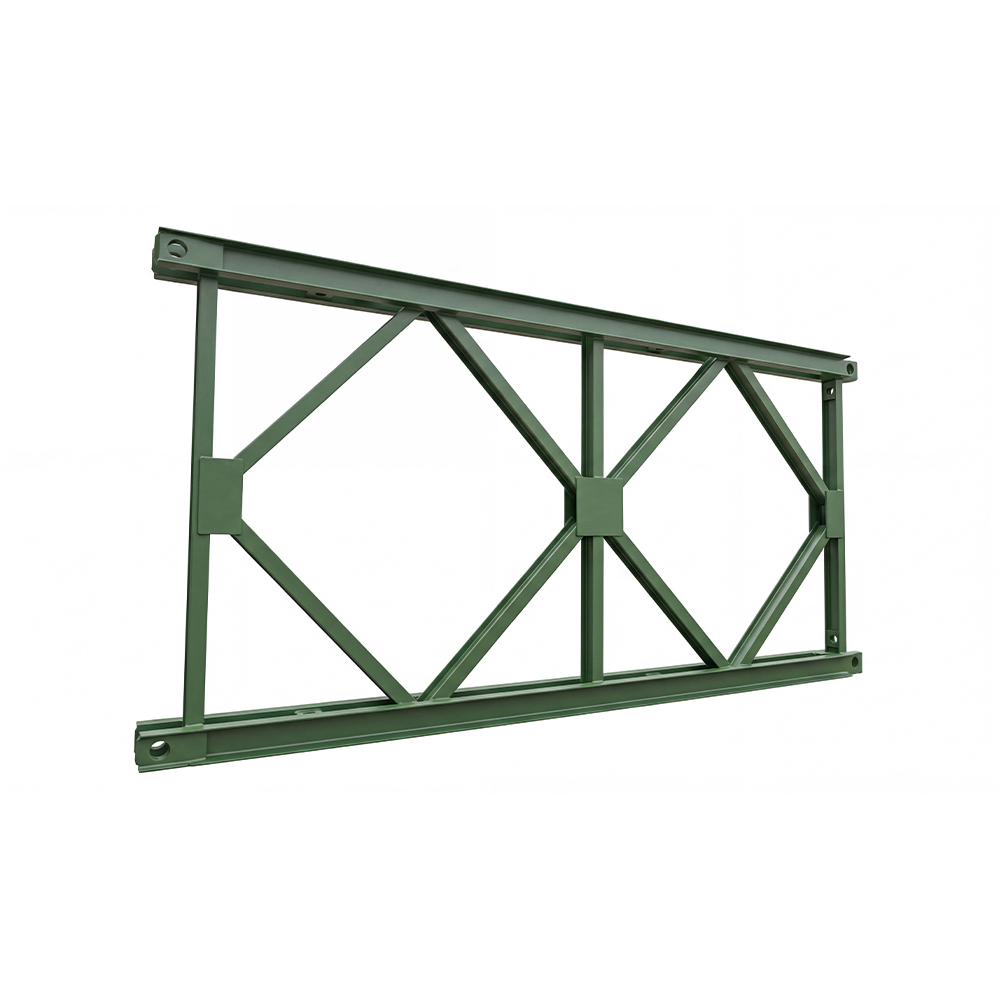 Type 321 Bailey Bridge Panel with Standardized DimensionsThis Type 321 panel is the closest to the original design, offering interchangeability across batches. Its welded cross-shaped structure provides stable load-bearing performance, making it a reliable choice for rapid replacement in construction or flood relief.View Product →
Type 321 systems are the closest to the original design. Their panels, crossbeams, and support frames are manufactured to standard dimensions so that components from different production batches can be mixed in one bridge. For a construction site or a flood relief operation, that means a damaged panel can be replaced in minutes without modifying adjacent components.
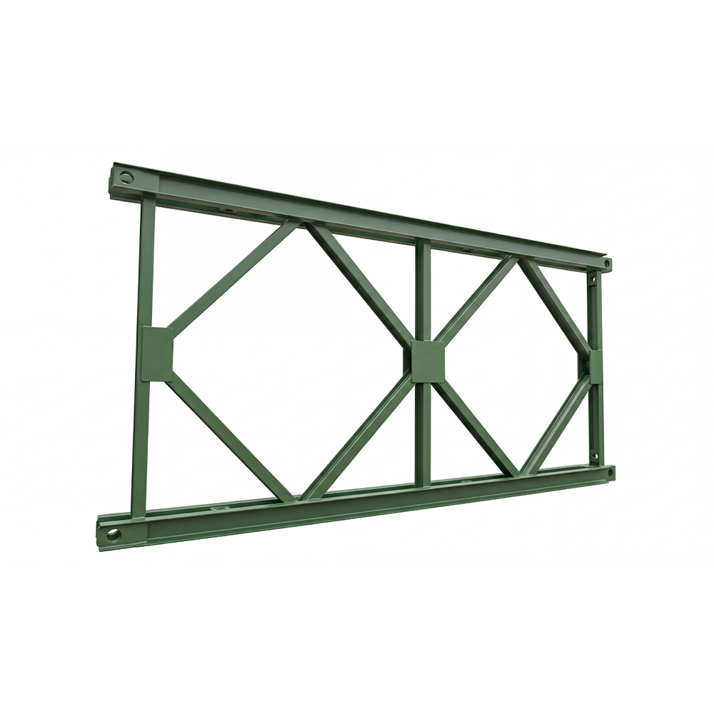
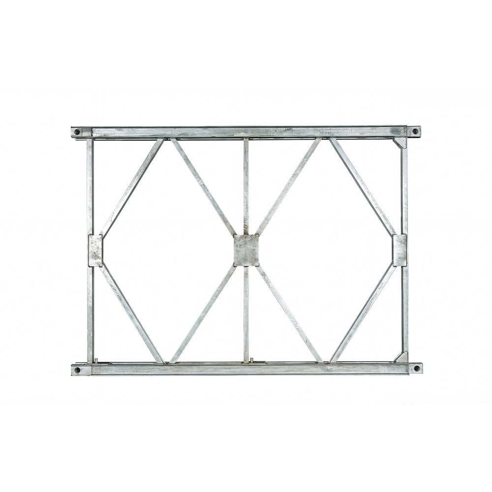 HD200 Bailey Bridge Panel for Heavy-Duty LoadsThe HD200 panel features increased length and width to improve bending resistance and reduce deflection. Designed for heavier axle loads and longer spans, it suits main road diversions and sites with heavy construction traffic.View Product →
HD200 systems scale the same concept to heavier duty work. Taller panels and heavier chords carry larger axle loads and permit longer unsupported spans, which is why HD200 is often chosen for main road diversions, railway access, and sites where construction traffic includes dump trucks and concrete pumps. The system still assembles by hand tools, but the engineering margins are built for continuous service rather than temporary use.
In practice, the choice between Type 321 and HD200 comes down to the loading envelope and the expected service life. A temporary access bridge for light vehicles on a building site may be best served by Type 321, while a haul road crossing that will carry loaded quarry trucks for two years will justify the additional cost of an HD200 structure.
What to Check Before You Specify a Modular Bailey Bridge
The 1941 prototype test is a useful reminder that a bailey bridge's real strength comes from its joints and tolerances, not from the mass of steel in each panel. Every procurement decision should therefore start with the following checks.
Verify Pin and Panel Condition
The pins transfer all load between panels. Any elongation of the pin holes, corrosion on the pin surface, or cracking in the panel chord reduces the effective capacity of the whole bridge. Insist on documented inspection records and, for second-hand panels, ask about the original production date and service history.
Confirm Interchangeability with Existing Inventory
If you already own panels or plan to mix new with used, confirm that the new supply matches the same system standard. Type 321 panels are not interchangeable with HD200 panels, and even within one system, minor differences in manufacturing can cause fit problems.
Check Deflection and Pre-Camber Requirements
Long spans deflect noticeably under load. For bridges carrying vehicles, excessive deflection creates a poor ride and accelerates wear on the deck. A pre-cambered truss option is worth specifying when the bridge will stay in service for more than a few months or when deck settlement is a concern.
 Pre-Cambered Bailey Truss for Large-Span StabilityThis pre-cambered truss compensates for self-weight and load deflection, offering deformation resistance for demanding large-span applications. Standardized joints and integrated pre-arched structure support complex stress conditions, though calibration is required before use.View Product →
Plan for Erection and Support Services
The prototype could be launched by hand because it was light. Larger HD200 systems need more manpower, more rollers, and sometimes a crane for panel handling. Ask your supplier how their core products and technical support cover site erection, and whether they can provide a full design and installation package.
The 1941 prototype test proved that a handful of standardized steel panels could form a bridge strong enough for modern armor. That principle has not changed. What has changed is the range of options available: different panel systems for different load classes, pre-cambered trusses for deflection control, and support components for every stage of erecting. By understanding what the prototype demonstrated, and by checking the details that matter, you can choose a bailey bridge that will perform safely, efficiently, and predictably, whether it is for a two-week emergency crossing or a two-year haul road.
If you are planning a temporary or semi-permanent bridge, start by reviewing your load requirements, site access, and installation budget, and consult an experienced manufacturer before locking in a system. The right modular bridge is the one that matches the conditions on your site, and the engineering principles behind it remain as sound today as they were when that Mark V tank rolled onto the prototype in 1941.


 Français
 Español
 عربى
عربى